
WIPL-D Pro CAD is a modeling and simulation environment uniting versatile, yet simple geometry modeling, with signature WIPL-D simulation accuracy.
Complex simulation structures and scenarios occurring in modern EM applications can be constructed using built-in drawing primitives or geometries imported from other modelers. A set of powerful, carefully selected commands complements the user-friendly modeling environment and makes the manipulations of the model parts easy and intuitive. The model geometry is meshed automatically using inhouse, all-quad mesher optimized for Higher Order Basis Functions (HOBFs) producing high quality mesh regardless the potentially high complexity of the model in hands and with very little user interaction required. Finally, in the simulation phase, WIPL-D Pro kernel is invoked to simulate the meshed structure.
Check our video tutorials to quickly grasp the essentials on working with WIPL-D Pro CAD.
Native Geometry Modeling
WIPL-D Pro CAD modeler uses the modeling approach common to most CAD solid modelers. Rich choice of 2D and 3D primitives, Boolean operations, basic and advanced options when copying or moving items, coordinate system transformation, selection options, snapping, cropping, sweep, loft and many other tools are all available to conveniently build and refine the parts of a model using native WIPL-D Pro CAD geometry editor. A sequence of the commands used to create a model is recorded and stored in an ASCII file. The sequence, casually called a History list, can be accessed and modified directly from the model editor which could be regarded as an alternative way of editing a model. Furthermore, a text file can be edited externally offering the possibility to modify or even create from scratch a model from another program or scripting language. Automatic inspection tools can be used at any stage to check the model for geometry or topology errors on one side, or related to material inconsistencies on the other side and to automatically resolve the ambiguities.

Geometry Import from Various CAD Formats
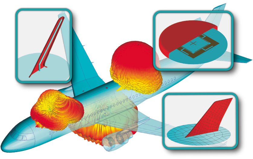
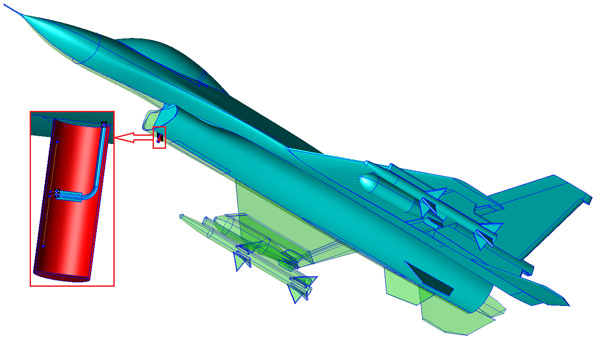
A modern EM modeling scenario can frequently be sophisticated and complex, yet requiring a high accuracy of EM simulations. The high accuracy in that case demands that the particular environment of interest is precisely recreated when building the simulation model. Such an EM environment typically combines several parts not necessarily all related to EM modelling background. A typical example could be a class of problems related to Antenna Placement where an antenna is designed to work on board an aircraft, ship, car or some other platform like laptop or mobile phone which are all usually modeled using mechanical CAD tools.
Many popular CAD formats, including IGES, STEP, CATIA to name just a few, are available for import/export with WIPL-D Pro CAD. An imported model usually must undergo some modifications before it becomes simulation ready. The first step in the preparation of an imported model is the healing of the irregularities. The irregularities are automatically recognized and marked in WIPL-D Pro CAD, and a set of advanced tools for healing, simplifying and sewing is available. The next step in preparation of the model is removal of the details irrelevant for EM simulation. Rich set of repair and rebuild tools including: fill hole, remove hole, remove feature, remove blend, delete open loop and many others make this process relatively simple. The final step of elimination of the small features is performed during the meshing process, where the details with a size below user-defined defeature tolerance are automatically eliminated.
A multilayer model can be build automatically starting from an imported DXF/DWG file, which comes very handy when working with PCB, LTCC, MMIC, thin film or a similar multilayer technology.
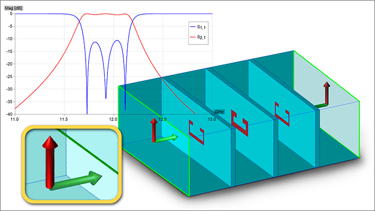
Waveguide Ports and Loads
In WIPL-D Pro CAD a model can be fed using several excitation options. In addition to the feeders available in WIPL-D Pro, such as delta generators, TEM frill generators, uniform plane waves, far field sources, in WIPL-D Pro CAD user can use waveguide ports. Supported port technologies are Rectangular Waveguide, Circular Waveguide, Coaxial Waveguide and Microstrip. Similarly to the mechanism of adding the ports, waveguide or microstrip loads can be added to terminate the circuit. A user can select between open, short or matched load.
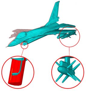
Mesh
In WIPL-D Pro CAD environment a model is meshed by invoking in-house developed quadrilateral mesher optimized for HOBFs. The meshing algorithm minimizes number of mesh elements and accordingly the number of unknowns. The meshed structure resembles the original model geometry with negligible distortion while keeping the favorable shape of the quads. Large mesh elements are automatically created on flat or mainly smooth model surfaces, while small mesh elements are created on model parts where small details and features are present. Elongated mesh elements are created over the model parts which are flat or smooth along one axis and curved along another. Accordingly, the mesher yields models with both large and small mesh elements as required for optimum operation of the simulation core. The mesh elements can be up to two wavelengths by two wavelengths in size with the order of approximation adaptively determined between 1 and 8 for each element.
For most EM problems the automatic meshing produces high quality mesh and the user interaction is not required. However, there is a possibility to influence the meshing process through user-controlled meshing parameters. The control is narrowed down to several parameters only, so that even an unexperienced user can successfully steer the meshing process in the right direction. To perfect the mesh, the corresponding parameters can be changed either globally or locally.
Integration with WIPL-D Pro
The process of meshing a model is in fact a process of converting the 3D solid model from WIPL-D Pro CAD into WIPL-D Pro native format. A meshed model can be edited using WIPL-D Pro editor allowing a certain degree of freedom to intervene with the outcome of the automatic meshing process. The light modifications of the automatically generated mesh can sometimes increase the accuracy or reduce the simulation time.
Any model created in WIPL-D Pro editor can be imported into WIPL-D Pro CAD. For example, an antenna can be imported and attached to a platform in a single click using advanced alignment options together with a number of coordinate system transformations.