
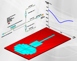
WIPL-D Microwave Pro is a linear circuit simulator which can be used for design and simulation of microwave circuits, components, and antennas. A user friendly and intuitive schematic capture makes the circuit modeling easy and versatile. The versatility is further busted by rich choice of circuit elements that can be included in the schematic. A circuit element can belong to any of the following groups:
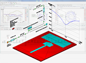
An element from the library of predefined components coming with the software installation. The component library includes closed-form models of microstrip, stripline, coplanar waveguide, rectangular waveguide and coaxial circuit elements. The closed-form models provide a reasonable accuracy with element characteristics calculated based on an approximate analytical expressions. They are a good choice where the speed of the computations is important. Alternatively, a predefined WIPL-D Pro EM model can be used bringing ultimate accuracy of EM simulations to the circuit analysis. An EM model is associated with each closed-form model where such a link is appropriate and a modeling option can be switched from analytical to EM with a single click. In addition to the distributed circuit elements, lumped elements and a number of ideal devices are available in the component library.
A user defined composite metallic and dielectric WIPL-D Pro 3D EM component created directly from Microwave Pro or prepared earlier using WIPL-D Pro editor and imported into the circuit schematic. In the latter case, the component can be solved prior to import and the results of the simulation preserved during import so that the subsequent circuit simulations do not require the repeated simulation of the imported EM component. This option allows import of very complex and electrically large structures as circuit elements while keeping the overall simulation time short.
An external data file in Touchstone format typically used when working with output data from another program, data sourced from a component vendor, obtained by measurements etc.
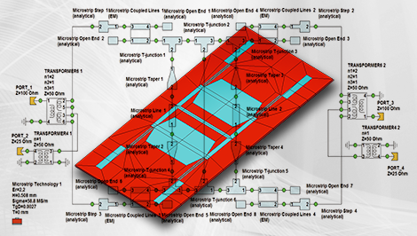
Combining elements from different groups within the same schematic and mixing analytical and EM models taking the benefits of both worlds, speed and accuracy as engineering judgement suggests, are the basic strengths of the Microwave Pro simulator when designing:
- Linear amplifiers
- Small signal oscillators
- RF and microwave filters
- Resonators
- Matching networks
- Antennas with matching structures
- Phased arrays with feeding structures
- Directional couplers
- Power dividers
- Connectors
Furthermore, the possibility to calculate a radiation pattern of an antenna or an array connected to a matching or feeding network and calculation of near field distribution greatly simplify simulation and optimization of various complex antenna scenarios when combining the circuit and 3D-EM solver is required, such as:
- Microstrip antennas embedded in finite lossy dielectric/magnetic materials,
- Horn-type feeds for reflector antennas,
- Phased arrays along with their matching circuitry, and
- Handset antenna in the vicinity of human head.
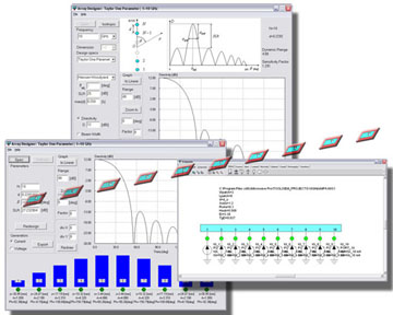
Array Designer
Array Designer is an add-on tool for WIPL-D Microwave, which helps design antenna arrays. For a given array element 3D EM model and radiation pattern specification, Array Designer computes (1) amplitudes and phases of feeding signals and (2) distances between array elements. In addition, at each design step, array factor is visualized.
Array Designer creates the best possible initial array design, with minimum number of elements. After obtaining the initial design, the user can interactively adjust design parameters and instantly see the updated array factor plots.
Currently, Array Designer provides Uniform amplitude, Windowed (featuring 15 window functions), Dolph-Chebyshev, Taylor, Schelkunoff, Fourier transform and Woodward-Lawson distributions for linear equally-spaced arrays. Both voltage and current excitations are supported.
For an arbitrary user-specified array element 3D EM model, Array Designer generates a parameterized schematic. The schematic representation of the antenna array performs full 3D simulation on-the-fly and is suitable for analysis and optimization in WIPL-D environment. WIPL-D Microwave’s powerful Smart Simulation feature greatly reduces simulation time for 3D EM models of large arrays.
The user-friendly interface greatly improves design efficiency and offers design flexibility, which makes Array Designer a useful tool for RF/microwave engineers and practitioners.
Features at a Glance
- Computes amplitudes and phases of feeding signals anddistances between array elements for a given radiation pattern specification
- User-friendly GUI with a straightforward two-stage design
- Designs linear equally-spaced arrays with following distributions:
- Narrow-beam low side lobe (windowed, Dolph‑Chebyshev,Taylor)
- Null placement (Schelkunoff’s polynomial method)
- Beam shaping (Fourier transform, Woodward-Lawson)
- Designs broadside, end-fire and increased directivity(Hanson‑Woodyard) arrays
- Generates a parameterized schematic for an arbitraryuser‑specified array element 3D EM model
- Schematic representation performs full 3D simulation on-the-fly and is suitable for analysis and optimization in WIPL‑D environment
Filter Designer
Filter Designer automates the design of lowpass, highpass, bandpass and bandstop filters of Chebyshev and Butterworth type to the required specification in a two-tier, wizard-like procedure. A user starts the design by entering the filter specifications through a magnitude/frequency insertion loss mask which is sufficient to calculate the initial filter order. In the cases where the user is not happy with passband or stopband performance of the initial filter, the specification can be re-entered or filter order and other design parameters adjusted manually in an interactive routine. The magnitude response plot updates automatically after each change of the filter parameters and the latest response can be easily compared against the specification mask. The process continues until the specifications are met and the final filter circuit is obtained.
The synthetized filter can take o form of microstrip, ideal transmission line, or lumped LC ladder network. For transmission line filters, supported design topologies include stepped-impedance, shunt stub, and capacitively-coupled resonator filters. The terminating impedances of the ports can be chosen to be different providing the possibility to use Filter Designer to design simple matching networks. The synthetized filter network can be exported to WIPL-D Microwave as parametrized circuit schematic and submitted to subsequent optimization and tuning.
Because of its user-friendly interface and a possibility to easily synthesize a number of frequently used filters, Filter Designer can be a useful assistant for students, RF/microwave engineers and practitioners.
 Features at a Glance
- User-friendly GUI with a straightforward, wizard-like two-stagefilter design
- Lowpass, bandpass, highpass and bandstop filters
- Chebyshev and Butterworth types
- Ideal LC lumped element, ideal transmission line and microstrip filters
- Stepped-impedance, shunt stub, and capacitively-coupledresonator transmission line filters
- Automatically generated parameterized WIPL-D Microwaveschematic
- Subsequent filter refinements powered by WIPL-D Optimizer
- On-the-fly validation of filter response during the design stages
- Final validation of the filter schematic via WIPL-D 3D EMcomponent characterization
- Different source and load resistances