Direction Finding Antenna (DFA)
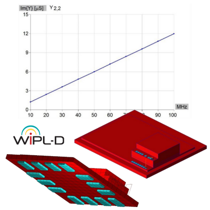
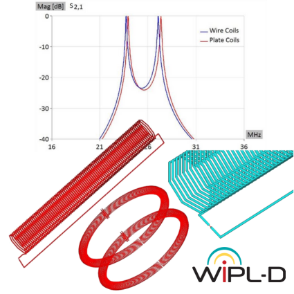
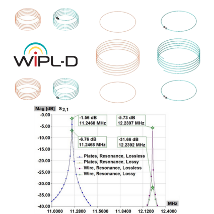
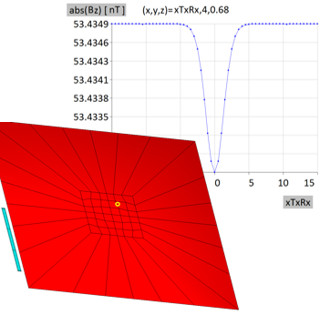
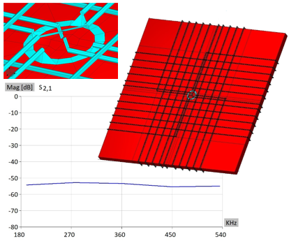
A magnetic antenna system, which has been patented by G. Wennerberg, could be efficiently used as a direction finding antenna (DFA). This magnetic antenna system represents an improved magnetic antenna, especially suitable for mounting on an aircraft as it does not include any moving parts.

In this application note we present simulation details for electrically small direction finding antenna comprising 2 coils wrapped around the magnetic material. Two wrapped coils are winded in the orthogonal direction. The smallest mesh element found in the DFA is about 0.2 mm long and it represents approximately 1/8,000,000 fraction of wavelength.

The DFA has been simulated using WIPL-D Pro, a mature, full wave 3D EM solver, based on method-of-moments (MoM). In general, MoM codes have been often challenged when a simulation model corresponds to a very small or moderately small device, such is the case with direction finding antenna presented here. For such a simulation, other numerical methods such as FEM or FDTD are widely used. However, in this particular application note, we demonstrate that this state-of-the-art MoM code can be used successfully and with high efficiency for simulating an electrically small structure.

The application note actually demonstrates that WIPL-D Pro can be used for simulation at extremely low frequencies where a typical MoM code is not typically used. In addition, it is shown that the special techniques for treatment of low frequency problems results in an extraordinary accuracy as the results remain accurate at the coupling levels down to -60 dB levels for coupling between the two antenna ports. Finally, it is shown that no expensive hardware is required as the simulations can be carried using standard desktop PC or laptop.

View PDF

On-Chip Capacitances

This report describes use of WIPL-D Software suite for analysis of self capacitance and the capacitances between the pads and associated connecting wires both being the parts of a relatively small chip (2-3 mm). The frequency range of interest is between 10 kHz and 10 MHz, which makes this on-chip capacitance calculation problem to be referred to as extremely low frequency problem.

WIPL-D Pro a 3D EM method-of-moments (MoM) based solver is typically used as high frequency simulator which can be used to simulate problems even in physical optics region. Nevertheless, providing that a special care is exercised, in terms of structure modeling and setting the project parameters, it can be successfully used for simulations at low frequency.

In this particular example, the chip geometry can be modeled in two ways-using WIPL-D Pro or using WIPL-D Pro CAD. When using WIPL-D Pro, the model is built from wires and plates, or using higher-level entities (objects). In that case building of a model is actually closely related to manual definition of the mesh. On the other hand, with WIPL-D Pro CAD a model is built from solid bodies using a choice of manipulation commands, and a model structure is meshed automatically. Models can be made from numerous built-in primitives or imported in popular CAD file formats. As the general chip geometry can vary from relatively simple to very complex, the modeling using WIPL-D Pro CAD has certain advantages.

In the entire simulation range, the behavior of the device is linearly proportional to frequency. Low frequency chip behavior can be obtained by extrapolation of result at higher frequencies. It is enough to perform this simulation of the chip at single frequency in the upper frequency bands and to assume that the same capacitance is preserved at lower frequencies.

In the particular case of low frequency simulations double precision with enhanced accuracy is required for highly accurate results. A standard desktop computer with 4 cores has been used resulting in simulation time in order of several minutes.

View PDF

Wire Thickness Effect in Wound Coils

This application note presents the effect of wire thickness to accuracy of electromagnetic simulation of wound coils. Two classes of examples will be discussed. The first class of examples relates to straight wound coils while the other class refers to toroidal wound coils.

The wound coil simulation examples will be used for direct comparison of physically identical coils modeled in WIPL-D using two modeling approaches – using wires or using plates. When using wires, a coil model is very easy to build as WIPL-D Pro helix built-in object can be used. However, a wire coil model applies thin wire approximation meaning that the current distribution does not change along the circumference of the wire but it changes only along the wire axis. Due to the approximation, simulations are very fast, but the accuracy could be compromised. The aim of this application note is to investigate if the thin wire model can be used when simulating the coils. Building the more accurate wound coil model with the plates, where the all components of the current are taken into account is more demanding.

The two wound coil models yield almost identical results although the completely different models have been used. Therefore, the thin wire approximation can be applied to coil wire objects without compromising the accuracy. The approximation significantly reduces simulation time and computer requirements. However, the thin wire coils model becomes less reliable as the frequency and winding density is increased.

Computer used in this application is regular desktop PC. All presented models of the coils are simulated efficiently. The wire coil models run in seconds, while the plate coil models run in minutes.

View PDF

Fast and Accurate WIPL-D Simulation of Wireless Power Transfer

This note explains how an inductive wireless power transfer (WPT) link can be simulated using WIPL-D Pro CAD, a full electromagnetic (EM) simulator and solid modeler design environment. The example used to demonstrate the features of the modeling environment has been taken from the literature. Two helical resonators have been coupled to input and output inductive loops respectively. As the numerical method implemented requires only the meshing of the boundary surfaces of the model parts, the simulations of the four inductors structure are very fast. The convergence of the results has been easily established by calculating the resonant frequency of a helical inductor identical to the one used in the particular WPT. Once the optimal meshing parameters are determined, speed and high accuracy of the analysis are both ensured. The accuracy of the solid (plate) inductor models has been confirmed high, while the much faster, thin wire approximation, is not adequate for this particular case.

Variation of the port impedances can be carried out to establish the optimum generator and source impedances providing efficient wireless power transfer. The results calculated using WIPL-D program suite are in excellent agreement with the data available from the literature.

All of the calculations have been carried out using standard desktop PC. The simulation time per one frequency point of the WPT link simulation is approximately 5 minutes.

View PDF

Buried Objects Detection via Magnetic Loop

This application note describes use of WIPL-D software suite for simulation of the coupling between an object buried in the ground and a magnetic loop above the ground. The note illustrates that variation of the coupling with the movement of the loop can be used to detect the buried metal objects. Simulations are carried out using WIPL-D Pro, a full wave 3D EM method-of-moment (MoM) based solver. The WIPL-D simulation software offers excellent speed, accuracy and produces reliable results, even at extremely low frequencies, such is the case described in this application.

Simulated scenario of buried objects detection via magnetic loop consists of thin aluminium plate located 3 m under the ground surface. Magnetic dipole is placed 2.2 m above the ground and swept above the buried aluminium strip in order to examine the change in the magnetic field value which could be used to detect a buried metal object.

Simulation was carried out at the operation frequency of 10 kHz. Small wire loop has the shape of the circle with radius set to 1/3 m (33 cm). The magnetic loop was moved in the interval [-15 m, 15 m] directly above the buried object to simplify the process illustration.

The simulation requires extremely low number of unknowns, under 500 and therefore the calculations could be very fast typically taking 1-2 sec on everyday desktop or laptop PC.

View PDF

Modeling Wires in Planar Spiral Coils

The application note Modeling Wires in Planar Spiral Coils demonstrates efficient WIPL-D software simulation at low frequencies in particular in the range 5-10 MHz. The modeling of the planar spiral coils, can be performed using two approaches. In the first approach a WIPL-D thin wire model is used to model the coils. With the thin wire model the circular component of the current is approximated as constant while current distribution along wire axis changes. The second modeling approach uses WIPL-D quadrilateral plates to model the coils. The modeling of the spiral coils is very simple and is based on built-in spiral/helix objects. The models can be made of thin wires, solid tubes and hollow tubes with wall thickness.

WIPL-D Pro CAD is extremely powerful state-of-the-art 3D EM solver, based on unique implementation of method-of-moments (MoM). It applies quadrilateral meshing and higher order basis functions. The later allows utilization of both, small and large mesh elements, as large as 2 lambdas. The computational method used by WIPL-D requires only the boundary surfaces to be meshed meaning that no boundary box is required to artificially limit the model space and that the problem size does not change when the distance between the coils changes.

The application note demonstrates that WIPL-D Software is very suitable for modeling and simulation of planar spiral coils. Metal parts of the coils can model as that they have been made of thin wires resulting in the extremely fast simulations with excellent accuracy, or as they have been made of metal plates providing very high accuracy. The simulation results suggest that the modeling of the coils using either hollow or solid planar spiral model produces almost identical results. WIPL-D specific equivalent radius calculus allows accurate simulation with lower number of segments. All simulations can be performed on standard laptop or desktop hardware. Even the effects of metallic tube thickness can be investigated easily. Simulation times are in the order of seconds for the thin wire approximation or the solid tube model, while they grow to a minute range for the hollow tube model.

View PDF

Coil with Continuously Variable Pitch

The models of the coil with continuously variable pitch were created using WIPL-D electromagnetic simulation software. In particular, WIPL-D Pro CAD software tool has been used to create the model, while WIPL-D flagship product WIPL-D Pro 3D EM solver has been seamlessly invoked to execute the simulations.

In WIPL-D Pro predefined primitive named Helix can be directly used to modeling a helix, coil or spiral inductor. However, if the winding of a coil is non-uniform, or is specified through an analytical expression, modeling is more convenient with WIPL-D Pro CAD.

The entire modeling process of the coil with continuously variable pitch consists of setting symbols, creating the wire according to the analytical specification of a non-uniform winding and subsequent sweeping of a cross section profile along the wire. The shape of the profile determines whether the coil would be modeled with infinitely thin conductors of with finite thickness conductors. The coil is then placed into a metallic frame. The feeding wire is also added. The entire process of creating the coil is straight-forward and can be completed very quickly.

Simulation of the model of the coil with finite metallization thickness typically lasts a couple of seconds per frequency for the case where a standard desktop PC or laptop is used, and is even shorter if a finite thickness is neglected.

View PDF

Wireless Power Transfer-The Example of Inductive Power Transfer in Cell Phone Charging

Wireless Power Transfer (WPT) basically involves a transmission of electrical energy from a power source to a load without usage of electrical conductors. In this application note we consider an example of a near field WPT, also known as Inductive Wireless Power Transfer, or IPT.

Various coil models and the results for an entire power charging scenario based on Inductive Power Transfer involving the coils are explained. A real-life scenario demonstrating how a smart phone can be inductively charged using a dedicated charging pad is presented. Realistic distances between the phone and the charging pad are considered ranging from several millimeters to a meter.

Only the radio frequency (RF) aspects of this scenario are investigated as it is sufficient to draw some important conclusions. The S-parameters calculated using an EM simulator are presented. WIPL-D software, a full wave 3D EM Method-of-Moments (MoM) based solver, has been used throughout this note for versatile geometry modeling and simulations. The simulations are very efficient even when using standard, inexpensive hardware.

View PDF

Verifying Accuracy for Inductive Loops with Lumped Elements

This application note aims at explaining analysis of simple wire loops (inductive in their nature) in WIPL-D software package. Special attention is devoted to the case when lumped elements are also included in the circuits.

Simple wire square loop is analyzed at 15.9155 MHz. Two loops are simulated with total circumference equal to 2 cm and 16 cm. The accuracy of EM simulation can be verified by checking the obtained values by using a number of free calculators available on the Internet. This calculator gives almost the same values as WIPL-D. These results illustrate accuracy of WIPL-D in determining low-frequency inductance. The simulation accuracy is verified with the same loops to which a lumped element is attached.

View PDF