MoM Simulation for Human Position Detection in IoT
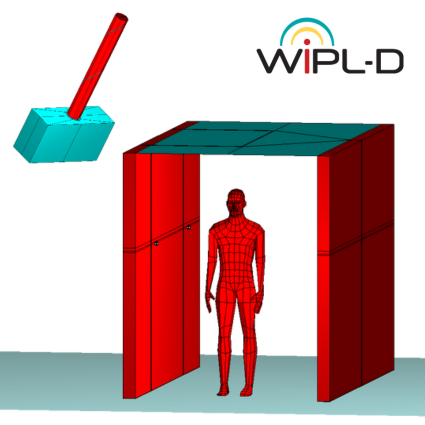
The 2.4 GHz IoT scenario in this note models a corridor with the ceiling and floor as metallic plates and an infinite PEC plane, a human phantom, and three Wi-Fi routers, one transmitting and the others receiving signals simultaneously. Received signals can detect human movement and determine precise position, as receiver currents vary with location. Simulation results can serve as reference for IoT measurements, enabling accurate position determination using a precomputed database. All simulations were performed using WIPL-D Software, a full-wave 3D EM Method-of-Moments solver with Surface Integral Equations. Despite usually requiring asymptotic methods, full-wave MoM was feasible, with about 37 minutes per phantom position.