Active Electronically Scanned Array (AESA)
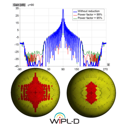
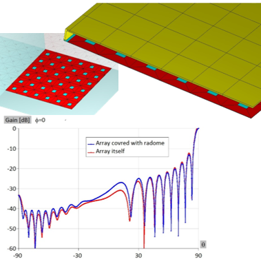
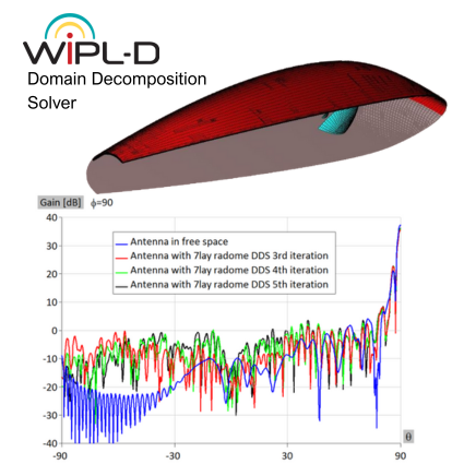
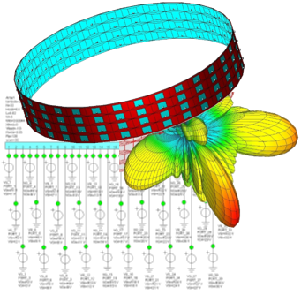
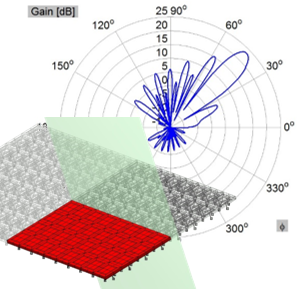
An important area of microwave engineering is the design of antenna arrays, especially in satellite and mobile communications. A specific type of the phased array antennas is active electronically scanned array (AESA).

WIPL-D Pro 3D EM solver is a full wave simulation tool based on Method of Moments. Numerous advanced techniques make it state-of-the-art: higher order basis functions, quadrilateral mesh (compared to more popular triangular), highly efficient CPU and GPU parallelized execution, using symmetry for both geometry and excitation etc. Due to very efficient simulation, WIPL-D Pro has been used to solve problems with hundreds of array elements.

WIPL-D asymmetry allows to simulate geometrically symmetrical arrays with arbitrary feed voltages. Such scenario also allows to run a single simulation and then later apply the appropriate generator voltages for different steer angles, without re-running EM simulation. The 128-element array (16×8 elements) of stacked patch antennas (3 dielectric layers) is fed by 4 coaxial probes per patch. The recommended hardware platform for this sort of simulation is a regular desktop PC, possibly enhanced with single inexpensive CUDA enabled GPU card. The simulation time is measured in minutes.

View PDF

Waveguide Slot Array 20x20

The application note presents efficient simulation of antenna array using WIPL-D Software. The waveguide slot antenna array with 400 elements (800 slots in total) is modeled and simulated by using WIPL-D Pro. Each radiating element consists of two shifted slots.

In order to save computational resources, two symmetry planes are applied. This means that only quarter of the array is simulated. Antenna array was simulated at 34 GHz.

The simulation was performed on standard desktop PC enhanced with single low-end GPU card. The matrix inversion was done both on CPU and GPU. The WIPL-D GPU solver was used and the app note shows the speed improvement when the matrix inversion is done by the GPU card.The average array element consisting of two slots requires only around 200 unknowns.

View PDF

Steering Array under 100 Lambda Radome via FGs

The primary function of radome is to protect an antenna system from environment with minimum impact to the electrical performances. In the case of electrically large radomes the techniques that are most often used are analytical and asymptotic techniques. In the number of cases, far better accuracy is required. WIPL-D advanced implementation of MoM, combined with inexpensive GPU platforms and Field Generators enabled such simulations.

Modeling of generic shape radome is very easy and fast using WIPL-D Pro CAD. Using WIPL-D Pro copy layer manipulation, adding multiple layers is done in a few seconds. The array in question is 100 lambda long with one or three dielectric layers.

The array radiation is steered across the entire surface of the radome. Instead to run multiple problems and reduce number of unknowns for each case, we use field generators. The simulation time is doubled at most for arbitrary number of directions. Here, 100 λ long quasi ellipsoidal shape radome is simulated in several hours, depending on the number of layers used.

View PDF

Radome Boresight

This application note demonstrates a study of the simulated radiation of electrically large waveguide antenna array through an electrically large highly transparent large radome in broad-side directions. Several effects lead to this highly advanced simulations: numerous WIPL-D simulation software features and the electromagnetic (EM) knowledge about functioning of the radomes.

The waveguide array itself is electrically large but can be relatively fast simulated on a standard desktop PC or laptop. This is possible due to efficient WIPL-D MoM implementation based on usage of higher order basis functions, quad mesh with elements up to 2 lambdas. The EM simulation can be further improved by using widely available inexpensive CUDA enabled Graphic Processing Unit (GPU) cards and the WIPL-D GPU solver.

Electrically larger 3-layer radome is added over the antenna. With the knowledge about principles of radomes and set of WIPL-D features (such as shadow reduction), GPU solver and inexpensive GPU workstation with 4 GPU cards, the EM simulation is carried out in reasonable engineering time (under 1h for the most demanding case). The three different scenarios are carefully carried out and number of unknowns adjusted: up, broadside and elevated broadside radiation.


View PDF

Microstrip Patch Array with Feeding Network

Microstrip patch antenna arrays are used to achieve much larger antenna gain and beam steering. In EM simulation, arrays require more sophisticated numerical simulation with appropriate hardware. Microstrip patch antenna array with feeding network is simulated using WIPL-D Pro – a MoM based full 3D EM solver. Such a simulation is possible owing to usage of higher order basis functions and quadrilateral mesh elements.

The simulation is carried out by using standard desktop PC. The code execution is efficiently parallelized at multicore CPUs. The improvement in speed when using low end GPU card is demonstrated. In terms of WIPL-D simulation, the array simulated in this application note can be considered as small or moderate. Large arrays can include hundreds of array elements.

View PDF

Radome Run Applied to Transparent Radome over FGs

In realistic antenna placement problems, outdoor mounted antennas are covered with radomes, which typically should affect performances as little as possible. WIPL-D team has significant experience in radome simulations, often electrically large in volume and surface. MoM code such as WIPL-D Pro is very suitable for radome simulations.

Radomes whose dimensions are measured in hundreds of wavelengths are very demanding and WIPL-D software suite offers several techniques to reduce number of unknowns. For such simulations, WIPL-D recommends usage of inexpensive GPU platforms. This application note focuses to reducing number of unknowns for single layer highly transparent radome by using Run Radome feature. Parts of radome having insignificant influence to the accuracy are identified and excluded. The reduction is controlled by user.

The results show huge reduction in number of mesh elements and number of unknowns, dramatically reduced simulation time, without impacting the accuracy of the results. Typical reduction in terms of number of unknowns is several times.

View PDF

Large Patch Array behind Car Bumper

The application note demonstrates excellent performance of WIPL-D suite for simulation of very large arrays of microstrip patch antennas. The microstrip with finite ground plane array has over 150 elements. Simulation frequency of interest is 70-80 GHz (specifically 77 GHz).

The model of the array is placed behind large metallic grill, which is then immersed into dielectric (plastic). This mimics the realistic situation where antenna array is covered by a car bumper.

A rather simplified formula estimates number of elements in patch array as number of elements multiplied by 500. This estimation applies when patch is placed above infinite PEC plane, and increases to 1000 when the ground is finite. Here, the number of unknowns is approximately 124,000, without any number of unknowns reduction applied. With the grill added, and again without reductions, the number raises to 190,000.

Finally, reduction of referent frequency, which should be set to only 32 GHz, is used for the plastic to which the grill is immersed. This yields in 290,000 unknowns.

All simulations are carried out on inexpensive server comprising of multiple core CPU and 4 low range Nvidia GTX GPU cards. The simulation times are couple of hours at most.

Domain Decomposition Solver (DDS) is intended for high frequency problems, since MoM poorly scales with frequency. This is an iterative solution. In our case, a fully convergent result is obtained after iteration #4 and beyond (the total of 15 iterations were examined). Previous iterations also show excellent accuracy, with each iteration being of approximately the same duration (under an hour).

View PDF

12x12 MPA Array Covered with Flat Radome

This application note presents how to use WIPL-D Pro as an efficient tool for full 3D EM simulation of arrays of microstrip patch antennas. The array consists of 12×12 elements. Using the symmetry, problem can be reduced to quarter of the full EM simulation (portion of 6×6 elements).

Array is built on 0.5 mm thick FR4 substrate (Er is equal to 4.3 and TgD is 0.02). Spacing between elements is set to 1.5 wavelengths (calculated in dielectric). Operating frequency is 4.4 GHz. Size of the patch is chosen as 0.45 wavelengths (both length and width). Feeding point is moved from the center for 0.3 x patch length. The antenna is covered by flat dielectric radome. Finite ground was extended slightly to 600×600 mm. Radome thickness is 2.3 mm (Er=3.2, TgD=0.025). The radome was placed 0.5 wavelengths away from the surface of the array (calculated in array substrate).

The PC used for simulation is regular inexpensive desktop computer equipped with inexpensive GPU card and increased amount of RAM. All simulation times are just a couple of minutes.

View PDF

Large Multilayer Radomes

Electrically large multilayer radomes represent important part of the realistic antenna structures. Thus, models of multilayer radomes are simulated by using full 3D electromagnetic software – the WIPL-D software which successfully exploits CPU multi-threading capabilities.

In this application note we demonstrated that number of unknowns can be significantly reduced for large multilayer radome simulations by using WIPL-D built-in techniques. The process of was done without impacting the accuracy of the results. Typical reduction in terms of number of unknowns is several times (for the smaller 3-layer radome the reduction is above 3 times).

We also present the efficient utilization of Domain Decomposition Solver (DDS), which can be used in solving electrically very large problems, for radome simulations. Starting from the 4th iteration, DDS result showed fine accuracy compared to the full-wave Method-of-moments (MoM) solution. The comparison was done for a smaller 3-layer radome which basically reaches the limits of MoM solution (for the reasonable simulation time). Based on this, we proceed to the simulation of much larger, numerically more demanding model of the 7 layer radome. DDS allows such a simulation for acceptable simulation time on moderate CPU-based platform.

The final simulation that was performed requires over 2 million unknowns. While it is still beyond the reach of full wave MoM, it can be very efficiently solved by DDS.

View PDF

Microstrip Patch Array Printed on Cylinder

The aim of this application note is to demonstrate efficient modeling and simulation of an antenna array by using WIPL-D software (WIPL-D Pro, WIPL-D Microwave and WIPL-D Optimizer). The result of interest is radiation pattern of the array.

After optimizing characteristics of single patch antenna, the array is created mainly through WIPL-D Pro Manipulations. The 3D EM models are simulated and imported into the WIPL-D Microwave.

The microwave circuit is simulated during the optimization, but the simulation of full wave 3D EM models was run only once (the so called co-simulation). After that, each co-simulation run lasts less than 2 seconds. This allows huge number of optimization cycles to adjust the main lobe and suppress side lobes.

All the simulations were carried out on regular desktop. In order to speed up the most demanding stage of the MoM simulation (for electrically moderate and large models) the matrix inversion, WIPL-D GPU Solver was used. The PC was enhanced with inexpensive low-end Nvidia GPU card.

View PDF

Waveguide Slot Array

Slotted waveguide arrays consist of a number of slots cut into the walls of a waveguide forming an array with the slots acting as individual radiating elements.

The specific design task here is a 10-element transversal slot array cut into the upper wide side of a WR-51 standard rectangular waveguide. The operating frequency is the center of the K band,  8.5 GHz.

Single slot model requires only 231 unknowns thanks to higher order MoM applied in WIPL-D Pro 3D EM Solver. The array model is built by using the single slot model and applying a single Copy operation to create the other 9 array elements. That model requires only 1149 unknowns. Single slot simulation lasts under a second on a standard desktop PC or any low-end laptop with dual or quad core CPU, while the array simulation lasts only a few seconds.

View PDF

Spherical Radome over Circular Horn

Radome represents enclosure protecting usually a radar antenna. The radomes are designed in such manner that they minimally influence operating characteristics of the protected antenna. Ideally, radome should be transparent for the EM ways penetrating it. Radome and antenna are usually simulated as the inseparable components of antenna system.

In this application note, demo model of the radome and the horn antenna are simulated in WIPL-D Pro, a full 3D EM Method-of-Moments based solver. The demonstration model of the radome represents model of monolithic radome used as a cover for simple circular horn antenna. The main focus of this application note is to show how fast and accurate the horn antenna covered by radome can be simulated using WIPL-D software.The operation frequency is 9.5 GHz. Computer used for these simulations is standard desktop, with simulation time of just a couple of seconds. Presented results clearly show influence of dielectric applied within the electrically thin radome – only lower levels of the radiation pattern are significantly disturbed.

View PDF