Printed Volcano Smoke Antenna
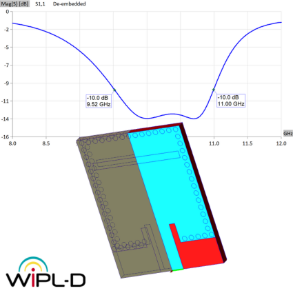
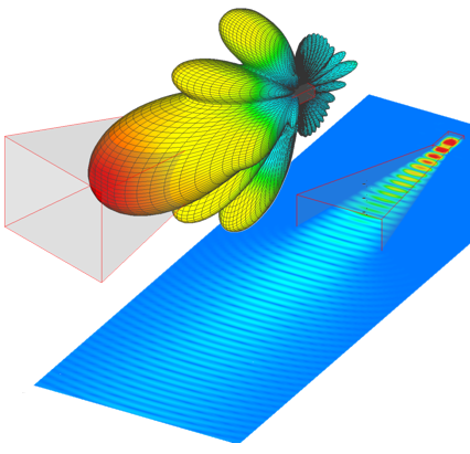
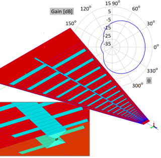
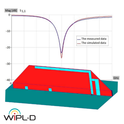
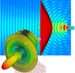
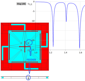
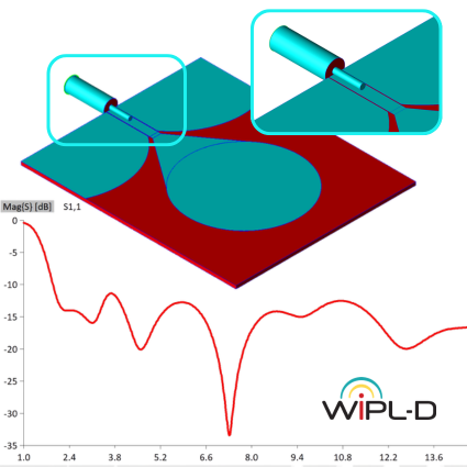
This note presents the modeling and simulation of a Printed Volcano Smoke Antenna using WIPL-D Pro CAD. The antenna is analyzed from 1 to 15 GHz, with return loss, VSWR, and radiation pattern as the results of interest. Suitable for WLAN and UWB applications, the antenna is printed on a dielectric substrate with relative permittivity Er = 2.78 and a thickness of 0.8 mm. The model consists of a printed radiating patch fed through a coplanar waveguide and coaxial cable. Emphasis is placed on the Symmetry feature, which enables efficient modeling by reducing the number of unknowns while maintaining identical results. Using a half-model approach, the simulation demonstrates a 54% reduction in total simulation time compared to the full model.