Differential Filter Design and Optimization
27-Nov-2016

27-Nov-2016
 This note explains how to analyze and optimize a general differential microwave circuit using WIPL-D design environment. Weather it is the circuit or EM component the differential/common mode analysis can be carried out within WIPL-D Microwave Pro by adequate connection of several transformer elements to convert single-mode S parameters to differential/common mode S Parameters.
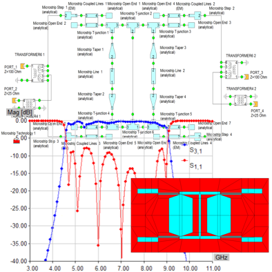
The innovative differential filter taken from the literature has been used to illustrate the analysis and optimization procedures. The filter has been analyzed as ideal transmission line circuit, as microstrip schematic and as 3D EM component. Converting ideal transmission line circuit into the realistic microstrip layout, causes several parasitic effects to occur, not included in the ideal model. The optimization process was applied to EM model since it includes all of the parasitic effects.
The modeling method demonstrated here can be applied to directly obtain differential/common mode S parameters of other differential components, such as amplifiers, couplers, antenna matching networks, etc.
Section: Microwave Circuits
For full version of the document, please check the following pdf.